6. Operation
-
Remote Control:
The remote connectors of RRDE-3A control rotation and gas purge functions by an external unit. The RRDE-3A is designed to be controlled by the appropriate commands from the potentiostats. When it does not use, make sure that power is turn out. These functions are activated either by a TTL signal or from any other controllers.
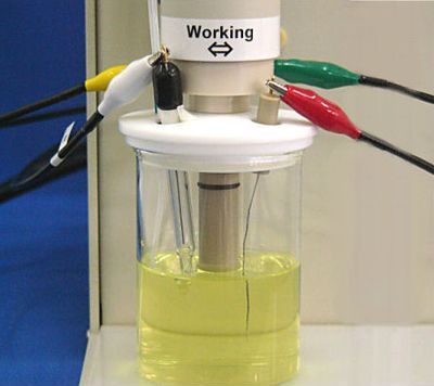
Each connector is connected properly with each electrode, and make
sure that its electrical connection is confirmed.

No.1 is disk electrode and No.2 is ring electrode. Each electrical
connection is completely independent.
-
Placement of the front panel components in RRDE-3A:
| 1. Digital rpm display 2. rpm LED: The LED is flushing when speed control is turned on for sample vial,either remotely or manually 3. Rotation speed (Set, Local, Remote) switch 4. Digital switch to set rotation speed (X10) 5. Purge LED: The LED is flushing when gas purge is turned on for sample vial, either remotely or manually 6. Gas purge (Set, Local, Remote) switch 7. Digital switch to set purge time 8. Gas purge control knob 9. Motor shaft assembly 10. Reference electrode 11. Counter electrode 12. Teflon holder 13. Plastic cell holder 14. Working electrode 15. Glass cell vial 16. Stainless steel plate 17. Base plate |
 |