11. DRE Disk replaceable electrode
The Disk Replaceable Electrode (DRE) has the Disk electrode
removable.
The replacement of the disk electrode is possible from both side,
front side and rear side. It makes possible to choose, according to
the condition required for your research purpose.
Features:
1. Assessment of the disk electrode using the same ring
electrode, could avoid the influence of the ring material and
dimension.
2. Removable disk and ring assembly make possible modification of
the electrode surface and polishing process, separately.
3. Disposable disk could be used.
DRE-PGK Pt ring/GC disk replaceable electrode kit

Component (from the left to right):
1. DRE-SPC Teflon spacer
2. DRE-GCD GC disk
3. DRE-PTR Pt ring assembly
∗For the release, in April, the DRE-GCD GC disk will be available.
∗∗DRE-GCD GC disk and DRE-SPC Teflon spacer will be available to be
sold separately.
DRE-DCP - Disk electrode polishing and exchanging tool kit

Component:
1. DRE-BLK Base block
2. DRE-SPS Spacer push tool
3. DRE-DPS Disk push tool
4. DRE-STP Stopper
5. DRE-DRS Disk remove tool
6. DRE-EPH Electrode polishing holder
Handling sketch of the DRE
The DRE-STP Stopper is screwed to the DRE-PTR Pt ring assembly.
It works for the adjustment of the height, when the DRE-SPC Teflon
spacer and DRE-GCD GC disk are attached.
In the DRE-BLK Base block, the “A” side is for the DRE-SPC Teflon
spacer attachment, and “B” side is for the DRE-GCD GC disk
attachment.

...after fixed and adjusted the height of the DRE-SPC Teflon spacer
in to the DRE-PTR Pt ring assembly, move the DRE-PTR Pt ring
assembly to the “B” side.
Put the DRE-GCD GC disk from the front (Fig. 1) and adjust it with
DRE-DPS Disk push tool (Fig. 2).
Take out from the DRE-BLK Base block and adjust the height with
DRE-STP Stopper and DRE-DRS Disk remove tool, until have the flat
surface (Fig. 3).
Front/Rear Assembly &
Disassembly
![]()
![]()
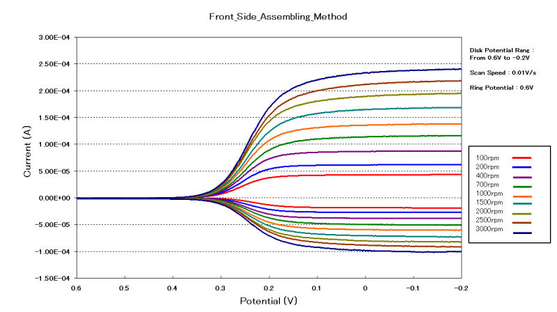
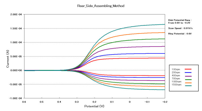
RRDE Disk replaceable electrode assessment test
The illustration in the section above shows the fitting of the
DRE-GCD Glassy carbon disk from the front side, however for the
performance test of the electrode, both way, front side and rear
side was done.
Typical test parameters are:
Working electrode : DRE-RRDE Pt ring GC disk electrode
Reference electrode: Ag/AgCl
Counter electrode : Platinum wire
Test solution : 2 mM Ferricyanide/1 M KNO3
Initial voltage : + 600 mV
Final voltage : - 200 mV
Scan Rate (Volt) : 10 mV/S
Rotation Rate : 100 to 3,000 rpm
Sensitivity : 10-5
2nd potential : + 600 mV
Fitting for the front side:
For the best understanding of the assembly, the video below shown step-by-step the assembly by front side:
Fitting for the rear side:
Explanation of the assembly by rear side:
Product information
For the DRE-PGK Pt ring/GC disk replaceable electrode kit:
| Catalog No. | Description |
| 013336 | DRE-PGK Pt ring/GC disk replaceable electrode kit |
| Component | |
| 013337 | DRE-PTR Pt ring assembly |
| 013338 | DRE-GCD GC disk |
| 013339 | DRE-SPC Teflon spacer (3pcs) |
| Optional items | |
| 013366 | DRE-AUD Au disk |
| 013367 | DRE-PTD Pt disk |
For the DRE-GCK disk replaceable electrode kit:
| Catalog No. | Description |
| 013362 | DRE-GCK GC disk replaceable electrode kit |
| 013364 | DRE-AUK Au disk replaceable electrode kit |
| 013365 | DRE-PTK Pt disk replaceable electrode kit |
| Components common for the kits | |
| 013361 | DRE-DAS Disk assembly |
| 013339 | DRE-SPC Teflon spacer (3pcs) |
| Optional items | |
| 013338 | DRE-GCD GC disk (included in 013362) |
| 013366 | DRE-AUD Au disk (included in 013364) |
| 013367 | DRE-PTD Pt disk (included in 013365) |
For the DRE-DCP Disk electrode polishing and exchanging tool kit:
| Catalog No. | Description |
| 013340 | DRE-DCP Disk electrode polishing and exchanging tool kit |
| Component | |
| - | DRE-BLK Base block |
| - | DRE-STP Stopper |
| - | DRE-DRS Disk remove tool |
| - | DRE-SPS Spacer push tool |
| - | DRE-DPS Disk push tool |
| - | DRE-EPH Electrode polishing holder |
Technical note
How to polish the DRE-PTR Pt ring assembly?
In the package, when you received the DRE-PGK Pt ring/GC disk
replaceable electrode kit, the DRE-PTR Pt ring assembly is setting
in the tube, fixed with a silicon rod to do not move.
Do not throw out the silicon rod!
It will be used for the polish of the DRE-PTR Pt ring assembly.
 |
 |
 |
|
Cut the silicon rod into 0.5 cm and insert into assembly
from the connect side. |
Push the silicon rod into the ring assembly by using DRE-STP slowly. Be care to keep the silicon rod surface flat or slight lower position than the Pt ring surface. Then follow the general electrode polishing procedure indicated in our website from PK-3 Electrode Polishing Kit. |
After polishing, screw the DRE-STP to push out the
silicon rod, removing it from the electrode side.
DRE-STP must be used for removing the silicon rod. Any
Pt ring damage, due to the use of other tool for the
removing of the silicon rod, is out of guaranty range. |
After finish the measurement, the video below shown the way for the disassembly the disk.